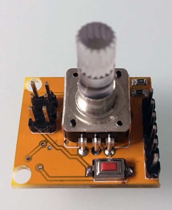
Attiny85 encoder pcb è il primo test eseguito sulla board che ho realizzato per leggere un encoder rotativo via I2C

e trasferire i dati ad un device in grado di fungere da Master IIC.
Programmazione ISP dell’Attiny85 encoder pcb
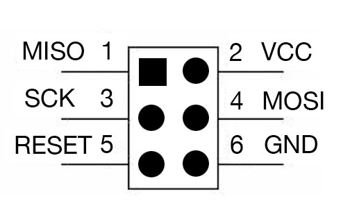
La programmazione del attiny85 encoder pcb devi eseguirla attraverso il connettore ISP predisposto sulla parte sinistra della board.
Lo standard del connettore è il medesimo presente su arduino:

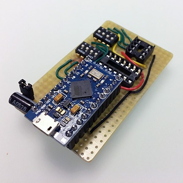
a cui ho collegato il mio programmatore, auto costruito:

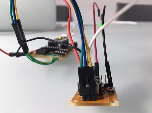
secondo quanto puoi vedere in questa foto:

ma puoi tranquillamente utilizzare un arduino come programmatore ISP per trasferire lo sketch che abilita l’Attiny85 encoder pcb ad essere utilizzato come Slave IIC.
Lo sketch Attiny85 encoder pcb
Dopo aver selezionato, nell’IDE arduino, l’Attiny85 con Internal Clock 16MHz puoi utilizzare lo sketch che hai già letto in altri articoli dedicati agli encoder rotativi attiny85 come slave IIC:
#define I2C_SLAVE_ADDRESS 0x8 // Address of the slave

#include <TinyWireS.h>
#include "avr/interrupt.h";

#define encA 3
#define encB 4
#define swtc 1

volatile byte currentValue = 0;
volatile int  lastEncoded  = 0;

void setup() {
    TinyWireS.begin(I2C_SLAVE_ADDRESS); // join i2c network
    TinyWireS.onRequest(requestEvent);

    pinMode(encA, INPUT);
    pinMode(encB, INPUT);
    pinMode(swtc, INPUT);
    digitalWrite(encA, HIGH);
    digitalWrite(encB, HIGH);

    GIMSK = 0b00100000;       // Enable pin change interrupts
    PCMSK = 0b00011010;       // Enable pin change interrupt for PB3 and PB4 and PB1
    sei();                    // Turn on interrupts
}

void loop() { TinyWireS_stop_check(); }

void requestEvent() {
    counter++;
    TinyWireS.send(currentValue);
    TinyWireS.send(digitalRead(swtc));
}

ISR(PCINT0_vect) {
  byte MSB = digitalRead(encA); //MSB = most significant bit
  byte LSB = digitalRead(encB); //LSB = least significant bit

  int encoded = (MSB << 1) |LSB; //converting the 2 pin value to single number
  int sum  = (lastEncoded << 2) | encoded; //adding it to the previous encoded value

  if(sum==0b1101||sum==0b0100||sum==0b0010||sum==0b1011) currentValue++;
  if(sum==0b1110||sum==0b0111||sum==0b0001||sum==0b1000) currentValue--;

  lastEncoded = encoded; //store this value for next time
}
trovi la descrizione dello sketch nell’articolo encoder attiny slave in cui lo sketch è stato spiegato linea per linea, in questa occasione è importante sapere che la linea 01 definisce l’indirizzo che devi configurare sul Master i2c che invia le chiamate.
Riporto anche lo sketch, di esempio, che ho utilizzato per la lettura dell’encoder rotativo con Arduino:
//Code for the Arduino Master
#include <Wire.h>

#define TARGET_ID 0x08

void setup()
{
 Wire.begin(); // join i2c bus (address optional for master)
 Serial.begin(9600); // start serial for output
}

void loop() {
  Wire.requestFrom(TARGET_ID, 2); // request 1 byte
                                                     // from slave device

  while(Wire.available() > 0) {
    byte i = Wire.read();
    byte sw = Wire.read();

    Serial.print( "Enc: " );
    Serial.print( i );
    Serial.print( " - Switch: " );
    Serial.println( sw );
   }

delay(100);
}
la cui descrizione e spiegazione puoi leggerla nell’articolo “AtTiny85 Encoder – Attiny Slave” e che produce come output il seguente:


 Il blog mauroalfieri.it ed i suoi contenuti sono distribuiti con Licenza
1 ping
[…] encoder attiny85 neopixel si distacca dall’utilizzo per cui è nata la rotary encoder attiny85 come hai letto nell’articolo di […]