
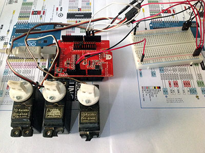
Oggi ho provato la Bluetooth Low Energy Shield servo ossia la Bluetooth Low Energy Shield con tre servocomandi di quelli comunemente usati in modellismo.
Il controllo dei servo, come sai, avviene mediante l’uso dei pin pwm di arduino e l’uso della classe Servo.h ed i servo standard sono in grado di eseguire movimenti in gradi da 0 a 180.
L’app per smartphone fornita dalla redbear lab ti offre la possibilità di controllare le uscite pwm anche come servocomandi inviando i gradi al posto dei valori 0-255 usati con i pin pwm.
Questo approccio rende più semplice lo sketch in quanto puoi usare direttamente il valore proveniente dall’App per inviarlo al servo senza dover intervenire per adattarlo da pwm a servo.
Il collegamento del Bluetooth Low Energy Shield servo
Il collegamento dei servo è illustrato in molti miei tutorial e non presenta differenze per questo progetto.
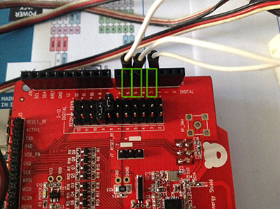
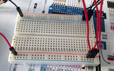
Ciascun servo deve essere alimentato da 4.8v a 6v per cui puoi utilizzare i 5v di arduino e presenta un pin di controllo che devi collegare ad una uscita pwm libera della Bluetooth Low Energy Shield servo, io ho usato i pin 3,5 e 6 come per il precedente articolo:
Important!
ATTENZIONE: alcuni servo hanno necessità di correnti elevate e l’alimentatore interno arduino non è in grado di erogare tutta la corrente richiesta. Questo comporta che i servo potrebbero non compiere alcun movimento o, al contrario, tremare non mantenendo la posizione corretta.
Sono tutti sintomi di scarsa alimentazione e ti consiglio di leggere come collegare i servo con alimentazione esterna.
I servo che ho utilizzato io sono poco onerosi dal punto di vista energetico e posso alimentarli tutti collegandoli ai 5v di arduino:
Lo sketch di test
lo sketch è sempre il “BLEControllerSketch” fornito con la libreria di controllo e gli esempi, lo riporto per conoscenza e ti invito a leggere la spiegazione line aper linea in questo articolo:
/*

Copyright (c) 2012, 2013 RedBearLab

Permission is hereby granted, free of charge, to any person
obtaining a copy of this software and associated documentation
files (the "Software"), to deal in the Software without restriction,
including without limitation the rights to use, copy, modify, merge,
publish, distribute, sublicense, and/or sell copies of the Software,
and to permit persons to whom the Software is furnished to do so,
subject to the following conditions:

The above copyright notice and this permission notice shall be included
in all copies or substantial portions of the Software.

THE SOFTWARE IS PROVIDED "AS IS", WITHOUT WARRANTY OF ANY KIND,
EXPRESS OR IMPLIED, INCLUDING BUT NOT LIMITED TO THE WARRANTIES OF
MERCHANTABILITY, FITNESS FOR A PARTICULAR PURPOSE AND NONINFRINGEMENT.
IN NO EVENT SHALL THE AUTHORS OR COPYRIGHT HOLDERS BE LIABLE FOR ANY CLAIM,
DAMAGES OR OTHER LIABILITY, WHETHER IN AN ACTION OF CONTRACT, TORT
OR OTHERWISE, ARISING FROM, OUT OF OR IN CONNECTION WITH THE SOFTWARE
OR THE USE OR OTHER DEALINGS IN THE SOFTWARE.

*/

#include <Servo.h>
#include <SPI.h>
#include <boards.h>
#include <RBL_nRF8001.h>
#include <services.h>
#include "Boards.h"

#define PROTOCOL_MAJOR_VERSION   0 //
#define PROTOCOL_MINOR_VERSION   0 //
#define PROTOCOL_BUGFIX_VERSION  2 // bugfix

#define PIN_CAPABILITY_NONE      0x00
#define PIN_CAPABILITY_DIGITAL   0x01
#define PIN_CAPABILITY_ANALOG    0x02
#define PIN_CAPABILITY_PWM       0x04
#define PIN_CAPABILITY_SERVO     0x08
#define PIN_CAPABILITY_I2C       0x10

// pin modes
//#define INPUT                 0x00 // defined in wiring.h
//#define OUTPUT                0x01 // defined in wiring.h
#define ANALOG                  0x02 // analog pin in analogInput mode
#define PWM                     0x03 // digital pin in PWM output mode
#define SERVO                   0x04 // digital pin in Servo output mode

byte pin_mode[TOTAL_PINS];
byte pin_state[TOTAL_PINS];
byte pin_pwm[TOTAL_PINS];
byte pin_servo[TOTAL_PINS];

Servo servos[MAX_SERVOS];

void setup()
{
  Serial.begin(57600);
  Serial.println("BLE Arduino Slave");

  /* Default all to digital input */
  for (int pin = 0; pin < TOTAL_PINS; pin++)
  {
    // Set pin to input with internal pull up
    pinMode(pin, INPUT);
    digitalWrite(pin, HIGH);

    // Save pin mode and state
    pin_mode[pin] = INPUT;
    pin_state[pin] = LOW;
  }

  // Default pins set to 9 and 8 for REQN and RDYN
  // Set your REQN and RDYN here before ble_begin() if you need
  //ble_set_pins(3, 2);

  // Set your BLE Shield name here, max. length 10
  //ble_set_name("My Name");

  // Init. and start BLE library.
  ble_begin();
}

static byte buf_len = 0;

void ble_write_string(byte *bytes, uint8_t len)
{
  if (buf_len + len > 20)
  {
    for (int j = 0; j < 15000; j++)
      ble_do_events();

    buf_len = 0;
  }

  for (int j = 0; j < len; j++)
  {
    ble_write(bytes[j]);
    buf_len++;
  }

  if (buf_len == 20)
  {
    for (int j = 0; j < 15000; j++)
      ble_do_events();

    buf_len = 0;
  }
}

byte reportDigitalInput()
{
  if (!ble_connected())
    return 0;

  static byte pin = 0;
  byte report = 0;

  if (!IS_PIN_DIGITAL(pin))
  {
    pin++;
    if (pin >= TOTAL_PINS)
      pin = 0;
    return 0;
  }

  if (pin_mode[pin] == INPUT)
  {
      byte current_state = digitalRead(pin);

      if (pin_state[pin] != current_state)
      {
        pin_state[pin] = current_state;
        byte buf[] = {'G', pin, INPUT, current_state};
        ble_write_string(buf, 4);

        report = 1;
      }
  }

  pin++;
  if (pin >= TOTAL_PINS)
    pin = 0;

  return report;
}

void reportPinCapability(byte pin)
{
  byte buf[] = {'P', pin, 0x00};
  byte pin_cap = 0;

  if (IS_PIN_DIGITAL(pin))
    pin_cap |= PIN_CAPABILITY_DIGITAL;

  if (IS_PIN_ANALOG(pin))
    pin_cap |= PIN_CAPABILITY_ANALOG;

  if (IS_PIN_PWM(pin))
    pin_cap |= PIN_CAPABILITY_PWM;

  if (IS_PIN_SERVO(pin))
    pin_cap |= PIN_CAPABILITY_SERVO;

  buf[2] = pin_cap;
  ble_write_string(buf, 3);
}

void reportPinServoData(byte pin)
{
//  if (IS_PIN_SERVO(pin))
//    servos[PIN_TO_SERVO(pin)].write(value);
//  pin_servo[pin] = value;

  byte value = pin_servo[pin];
  byte mode = pin_mode[pin];
  byte buf[] = {'G', pin, mode, value};
  ble_write_string(buf, 4);
}

byte reportPinAnalogData()
{
  if (!ble_connected())
    return 0;

  static byte pin = 0;
  byte report = 0;

  if (!IS_PIN_DIGITAL(pin))
  {
    pin++;
    if (pin >= TOTAL_PINS)
      pin = 0;
    return 0;
  }

  if (pin_mode[pin] == ANALOG)
  {
    uint16_t value = analogRead(pin);
    byte value_lo = value;
    byte value_hi = value>>8;

    byte mode = pin_mode[pin];
    mode = (value_hi << 4) | mode;

    byte buf[] = {'G', pin, mode, value_lo};
    ble_write_string(buf, 4);
  }

  pin++;
  if (pin >= TOTAL_PINS)
    pin = 0;

  return report;
}

void reportPinDigitalData(byte pin)
{
  byte state = digitalRead(pin);
  byte mode = pin_mode[pin];
  byte buf[] = {'G', pin, mode, state};
  ble_write_string(buf, 4);
}

void reportPinPWMData(byte pin)
{
  byte value = pin_pwm[pin];
  byte mode = pin_mode[pin];
  byte buf[] = {'G', pin, mode, value};
  ble_write_string(buf, 4);
}

void sendCustomData(uint8_t *buf, uint8_t len)
{
  uint8_t data[20] = "Z";
  memcpy(&data[1], buf, len);
  ble_write_string(data, len+1);
}

byte queryDone = false;

void loop()
{
  while(ble_available())
  {
    byte cmd;
    cmd = ble_read();
    Serial.write(cmd);

    // Parse data here
    switch (cmd)
    {
      case 'V': // query protocol version
        {
          byte buf[] = {'V', 0x00, 0x00, 0x01};
          ble_write_string(buf, 4);
        }
        break;

      case 'C': // query board total pin count
        {
          byte buf[2];
          buf[0] = 'C';
          buf[1] = TOTAL_PINS;
          ble_write_string(buf, 2);
        }
        break;

      case 'M': // query pin mode
        {
          byte pin = ble_read();
          byte buf[] = {'M', pin, pin_mode[pin]}; // report pin mode
          ble_write_string(buf, 3);
        }
        break;

      case 'S': // set pin mode
        {
          byte pin = ble_read();
          byte mode = ble_read();

          if (IS_PIN_SERVO(pin) && mode != SERVO \
                                && servos[PIN_TO_SERVO(pin)].attached())
            servos[PIN_TO_SERVO(pin)].detach();

          /* ToDo: check the mode is in its capability or not */
          /* assume always ok */
          if (mode != pin_mode[pin])
          {
            pinMode(pin, mode);
            pin_mode[pin] = mode;

            if (mode == OUTPUT)
            {
              digitalWrite(pin, LOW);
              pin_state[pin] = LOW;
            }
            else if (mode == INPUT)
            {
              digitalWrite(pin, HIGH);
              pin_state[pin] = HIGH;
            }
            else if (mode == ANALOG)
            {
              if (IS_PIN_ANALOG(pin)) {
                if (IS_PIN_DIGITAL(pin)) {
                  pinMode(PIN_TO_DIGITAL(pin), LOW);
                }
              }
            }
            else if (mode == PWM)
            {
              if (IS_PIN_PWM(pin))
              {
                pinMode(PIN_TO_PWM(pin), OUTPUT);
                analogWrite(PIN_TO_PWM(pin), 0);
                pin_pwm[pin] = 0;
                pin_mode[pin] = PWM;
              }
            }
            else if (mode == SERVO)
            {
              if (IS_PIN_SERVO(pin))
              {
                pin_servo[pin] = 0;
                pin_mode[pin] = SERVO;
                if (!servos[PIN_TO_SERVO(pin)].attached())
                  servos[PIN_TO_SERVO(pin)].attach(PIN_TO_DIGITAL(pin));
              }
            }
          }

  //        if (mode == ANALOG)
  //          reportPinAnalogData(pin);
          if ( (mode == INPUT) || (mode == OUTPUT) )
            reportPinDigitalData(pin);
          else if (mode == PWM)
            reportPinPWMData(pin);
          else if (mode == SERVO)
            reportPinServoData(pin);
        }
        break;

      case 'G': // query pin data
        {
          byte pin = ble_read();
          reportPinDigitalData(pin);
        }
        break;

      case 'T': // set pin digital state
        {
          byte pin = ble_read();
          byte state = ble_read();

          digitalWrite(pin, state);
          reportPinDigitalData(pin);
        }
        break;

      case 'N': // set PWM
        {
          byte pin = ble_read();
          byte value = ble_read();

          analogWrite(PIN_TO_PWM(pin), value);
          pin_pwm[pin] = value;
          reportPinPWMData(pin);
        }
        break;

      case 'O': // set Servo
        {
          byte pin = ble_read();
          byte value = ble_read();

          if (IS_PIN_SERVO(pin))
            servos[PIN_TO_SERVO(pin)].write(value);
          pin_servo[pin] = value;
          reportPinServoData(pin);
        }
        break;

      case 'A': // query all pin status
        for (int pin = 0; pin < TOTAL_PINS; pin++)
        {
          reportPinCapability(pin);
          if ( (pin_mode[pin] == INPUT) || (pin_mode[pin] == OUTPUT) )
            reportPinDigitalData(pin);
          else if (pin_mode[pin] == PWM)
            reportPinPWMData(pin);
          else if (pin_mode[pin] == SERVO)
            reportPinServoData(pin);
        }

        queryDone = true;
        {
          uint8_t str[] = "ABC";
          sendCustomData(str, 3);
        }

        break;

      case 'P': // query pin capability
        {
          byte pin = ble_read();
          reportPinCapability(pin);
        }
        break;

      case 'Z':
        {
          byte len = ble_read();
          byte buf[len];
          for (int i=0;i<len;i++)
            buf[i] = ble_read();
          Serial.println("->");
          Serial.print("Received: ");
          Serial.print(len);
          Serial.println(" byte(s)");
          Serial.print(" Hex: ");
          for (int i=0;i<len;i++)
            Serial.print(buf[i], HEX);
          Serial.println();
        }
    }

    // send out any outstanding data
    ble_do_events();
    buf_len = 0;

    return; // only do this task in this loop
  }

  // process text data
  if (Serial.available())
  {
    byte d = 'Z';
    ble_write(d);

    delay(5);
    while(Serial.available())
    {
      d = Serial.read();
      ble_write(d);
    }

    ble_do_events();
    buf_len = 0;

    return;
  }

  // No input data, no commands, process analog data
  if (!ble_connected())
    queryDone = false; // reset query state

  if (queryDone) // only report data after the query state
  {
    byte input_data_pending = reportDigitalInput();
    if (input_data_pending)
    {
      ble_do_events();
      buf_len = 0;

      return; // only do this task in this loop
    }

    reportPinAnalogData();

    ble_do_events();
    buf_len = 0;

    return;
  }

  ble_do_events();
  buf_len = 0;
}
Il video dimostrativo
Lascio alla tua fantasia la possibilità di inventare tanti progetti con questa shield e di suggerirceli nei commenti !!!

 Il blog mauroalfieri.it ed i suoi contenuti sono distribuiti con Licenza
2 commenti
Ciao, innanzi tutto vorrei ringraziarti pubblicamente, delle E_mail che mi hai spedito e quindi del tuo tempo che mi hai dedicato sebbene io fossi un estraneo. Spero adesso di poter condividere le mie idee e dare e apprendere consigli (dare sarà difficile…). dopo questa premessa, vi espongo la mia questione. Ho costruito un cingolato (spedirò le forto al più presto) e vorrei comandarlo. Come ti ho già detto, proverei con un arduino. il sistema voglio che sia ampliabile, quindi non vorrei utilizzare sistemi di radiocomandi “diretti” o sistemi WIRC, poichè non son oespandibili. quindi due motori che fanno avanzare il mio cingolato, 2 motori che inclinano il piano. Pe ora la mia idea era di prendere un ARDUPILOT e adattarlo, ma è troppo complesso. All’inizio ti chiedo se è possibile con un arduino accettare in ingresso un segnael PPM di 2 servi e emettere un segnale PWM per i motori. In questo modo all’interno dell’arduino posso miscelarli a piacere. In più mi servirebbero 2 uscite per servo comando RC per muovere l’inclianzione della piastra in avanti e indietro (per esempio se fa una salita…). Questi servi voorrei collegarli ad una unità di controllo (accelerometro + giroscopio) che ho visto che si può attaccare all’arduino. Si può fare?
grazie
Autore
Ciao Giuliano,
grazie per la voglia di condividere.
Attendo le foto e tutto il materiale che potrai produrre per descrivere al meglio il tuo progetto e pubblicarlo sul blog.
Quello che desideri realizzare penso sia fattibile con Arduino e ti consiglio di orientarti alla Leonardo in quanto dai miei esperimenti con WiRc si è rivelata maggiormente rispondente ai comandi inviati.
Un unica cortesia, i commenti inseriscili in articoli inerenti il tuo progetto così altri appassionati della medesima materia ti troveranno e potranno darti i loro consigli.