Circa un mese fa con l’avvicinarsi del Natale ti ho parlato di una scheda che mi ha molto colpito, la Rainbow Ring V3 e ne ho ordinata una da robot-domestici.it, insieme a molte altre shield e componenti di cui leggerai nei prossimi articoli e progetti.
La Rainbow Ring V3 è arrivata subito dopo le feste ma solo in questi giorni sono riuscito a dedicarle il tempo che avrei voluto.
Il contenuto della confezione della Rainbow Ring V3
il contenuto della confezione è:
- la Rainbow Ring V3 già assemblata con componenti SMD;
- n.1 connettore a 6 pin ad L da saldare in corrispondenza dei fori GND,DR,VCC,RX,TX,DTR;
- n.1 connettore a 5 pin ad L da saldare in corrispondenza dei fori GND,VCC,SDA,SCL,A3;
- n.1 connettore a 4 pin ad L da saldare in corrispondenza dei fori GND,VCC,SDA,SCL;
- n.2 connettori a 3 pin dritti da saldare in corrispondenza del connettore ISP;
- n.1 connettore a 3 pin ad L da saldare in corrispondenza dei fori D2,D3,D4;
- n.1 connettore a 2 pin ad L da saldare in corrispondenza del connettore Vin;
- n.1 cavo a 5 contatti ( Nero,Rosso,Giallo,Verde,Bleu ) per collegare la scheda ad Arduino od ad altri dispositivi.
Connetti e programma la Rainbow Ring V3
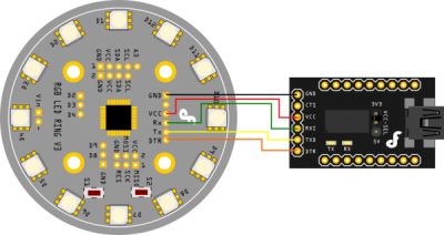
Come avrai già letto sulla guida ufficiale della Rainbow Ring V3 o sul mio articolo Rainbow LED Ring V3 Arduino – IDE 1.0 puoi programmare la Rainbow Ring V3 con un interfaccia FTDI o USB-Seriale, se ne possiedi una puoi seguire lo schema di collegamenti fornito dal produttore della scheda:
altrimenti io ti suggerisco di utilizzare Arduino come programmatore, in fondo la Rainbow Ring V3 è realizzata usando un ATmega168 come la LilyPad.
Ecco come eseguire i collegamenti:
Passo 1
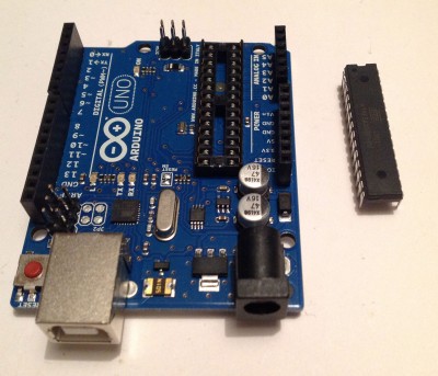
separa il microcontrollore ( ATmega328 ) dalla tua Arduino Uno:
Passo 2
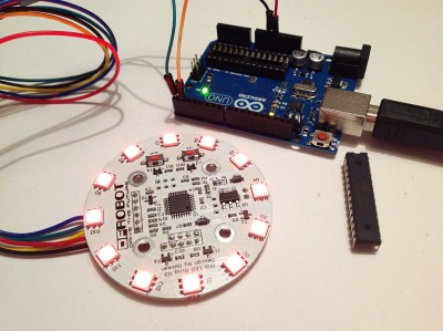
collega il connettore a 5 fili, compreso nella confezione della Rainbow Ring V3, alla scheda come in figura ed i terminali opposti: Nero,Giallo,Verde,Bleu ad arduino secondo la corrispondenza in figura:
Passo 3
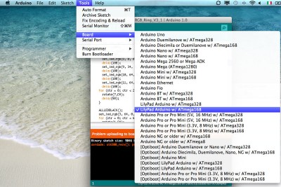
imposta nell’IDE 1.0 Arduino come Board la LilyPad ATmega168
Passo 4
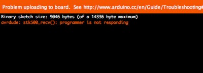
carica lo sketch di esempio fornito dalla DFRobot sulla Rainbow Ring V3. Potresti ottenere il seguente errore:
questo potrebbe essere legato al fatto che il pin di reset non è collegato, lo sketch dovrebbe essere stato caricato sulla Rainbow Ring V3 e potrai eseguirlo.
Lo sketch demo della Rainbow Ring V3
Sebbene lo sketch non lo abbia scritto io e tu possa scaricarlo dal sito del produttore della Rainbow Ring V3 lo riporto per completezza dell’articolo lasciando eventuali commenti ad un prossimo articolo quando sarò io a realizzare uno sketch con questa shield:
#include "RGB_Ring_V3.h"
#include <Wire.h>

int S1 = 3;
int S2 = 4;
int val1 = 0;     // variable to store the read value
int val2 = 0;
int turn = 0;

void setup() {
#ifdef UART
	InitUART();
#else
  Serial.begin(38400);           // start serial for output
#endif
	InitIO();

  Wire.begin(4);                // join i2c bus with address #4
  Wire.onReceive(receiveEvent); // register event

  pinMode(S1, INPUT);
  pinMode(S2, INPUT);
  digitalWrite(S1, HIGH);
  digitalWrite(S2, HIGH);
}

void loop() {
	uint8_t led;
  val1 =digitalRead(S1);
  val2 =digitalRead(S2);
  if(val1==LOW){  // ================演示代码
    uint16_t ctr;
    ALLLEDRED();
    delay(300);
    ALLLEDYELLO();
    delay(300);
    ALLLEDGREEN();
    delay(300);
    ALLLEDTURQUOISE();
    delay(300);
    ALLLEDBLUE();
    delay(300);
    ALLLEDFUCHSIA();
    delay(300);
    ALLLEDWHITE();
    delay(300);
    ALLLEDBLACK();
    delay(300);

    for (ctr = 0; ctr < 3; ctr++)    {
      sequence ();
    }
    ALLLEDBLACK();	// 测试单个LED
      set_led_rgb(0, 64, 0, 0);
      delay(100);
      set_led_rgb(1, 64, 32, 0);
      delay(100);
      set_led_rgb(2, 64, 64, 0);
      delay(100);
      set_led_rgb(3, 32, 64, 0);
      delay(100);
      set_led_rgb(4, 0, 64, 0);
      delay(100);
      set_led_rgb(5, 0, 64, 32);
      delay(100);
      set_led_rgb(6, 0, 64, 64);
      delay(100);
      set_led_rgb(7, 0, 32, 64);
      delay(100);
      set_led_rgb(8, 0, 0, 64);
      delay(100);
      set_led_rgb(9, 34, 0, 64);
      delay(100);
      set_led_rgb(10, 64, 0, 64);
      delay(100);
      set_led_rgb(11, 64, 0, 32);
      delay(100);
    for (ctr = 0; ctr < 24; ctr++)    {
      rotate(7,CW);
      delay(50);
    }

    ALLLEDBLACK();	// 测试滚动LED
    set_led_rgb(3, 64, 0, 64);
    for (ctr = 0; ctr < 60; ctr++)    {
      rotate(1,CW);
      rotate(3,CCW);
      delay(50);
    }
    ALLLEDBLACK();
    ALLLEDYELLO();
    delay(50);
    for (ctr = 0; ctr < 5; ctr++)    {
          swaywobble(50,CW);
    }
          ALLLEDBLACK();
          setwobble(0xFFFF);

    ALLLEDBLACK();
    for (ctr = 0; ctr < 3; ctr++)    {
      fader();
    }
          ALLLEDBLACK();
    for (ctr = 0; ctr < 3; ctr++)    {
      fader_hue ();
    }
          ALLLEDBLACK();
    for (ctr = 0; ctr < 400; ctr++) {
      color_wave (45);
    }
    for(ctr = 0; ctr < 5; ctr++) {
      disable_timer2_ovf();
      delay(100);
      enable_timer2_ovf();
      delay(100);
    }

	}else if(val2==LOW){	// ==============测试颜色代码
    switch (turn){
      case 1:
        ALLLEDRED();
        break;
      case 2:
        ALLLEDYELLO();
        break;
      case 3:
        ALLLEDGREEN();
        break;
      case 4:
        ALLLEDTURQUOISE();
        break;
      case 5:
        ALLLEDBLUE();
        break;
      case 6:
        ALLLEDFUCHSIA();
        break;
      case 7:
        ALLLEDWHITE();
        break;
      default:
        ALLLEDBLACK();
        break;
    }
    delay(200);
    turn++;
    if(turn==8) turn=0;

	}else{		// ================命令代码
		if(Command[0]>0XEF){
			if(Command[0]<0XFA){
                                setwobble(0X0FFF);
				switch (Command[0]){
					case 0xF0:
						if(Command[1]==1){
							enable_timer2_ovf();
						}else{
							disable_timer2_ovf();
						}
						Command[0]=0;
						break;

					case 0xF1:	//设置单个LED颜色
						set_led_rgb(Command[1], Command[2], Command[3], Command[4]);
						Command[0]=0;
						break;

					case 0xF2:	//设置单个LED单色
						set_led_unicolor(Command[1], Command[2], Command[3]);
						Command[0]=0;
						break;

					case 0xF3:	//设置全部LED同一颜色
						set_all_rgb(Command[1], Command[2], Command[3]);
						Command[0]=0;
						break;

					case 0xF4:	//设置全部LED同一单色
						set_all_unicolor(Command[1], Command[2]);
						Command[0]=0;
						break;

					case 0xF5:	//顺序转动单次
						rotate(Command[1], Command[2]);
						Command[0]=0;
						break;

					case 0xF6:	//设置亮度
						//
						Command[0]=0;
						break;

					case 0xF7:	//设置数组
						uint8_t w;
						for(w=0;w<__leds;w++)
							wobble_pattern_3[w]=(uint16_t)(Command[w*2+1]<<8|Command[w*2+2]);
						Command[0]=0;
						break;

					default:
						Command[0]=0;
						break;
				}
			}else{
				switch (Command[0]){
				case 0xFA:	//数组
					if(Command[1]>0){
						swaywobble(Command[1],Command[2]);
					}else{
                                                setwobble(0X0FFF);
						Command[1]=0;
						Command[0]=0;
					}
					break;

				case 0xFB:	// 暴闪
                    if(Command[1]>0){
    					disable_timer2_ovf();
    					delay(Command[1]);
    					enable_timer2_ovf();
    					delay(Command[1]);
                    }else{
						enable_timer2_ovf();
						Command[1]=0;
						Command[0]=0;
					}
					break;

				case 0xFC:	// 滚动
					if(Command[1]>0){
						rotate(RED, Command[2]);
						rotate(GREEN, Command[3]);
						rotate(BLUE, Command[4]);
						delay(Command[1]);
					}else{
						Command[1]=0;
						Command[0]=0;
					}
					break;

				default:
					Command[1]=0;
					Command[0]=0;
					break;
				}
			}
		}
	}
}

void receiveEvent(int howMany)
{
  uint8_t data;
  Serial.println("I received: ");
  ReceivePtr=0;
  while(1 < Wire.available()) // loop through all but the last
  {
    data = Wire.read();
    Serial.println(data, HEX);
    rx_buf[ReceivePtr]=data; // receive byte as a character
    ReceivePtr++;
    if(ReceivePtr==RX_MASK)  ReceivePtr=0;
  }
    data = Wire.read();
    Serial.println(data, HEX);
    if(rx_buf[0]==0xF8){
        uint8_t l=rx_buf[1];
        Wire.write(brightness[0][l]);
        Wire.write(brightness[1][l]);
        Wire.write(brightness[2][l]);
    }
    if((ReceivePtr<=COMMAND_SIZE) && (rx_buf[0]==data)) savebuff();

}
Il video dello Sketch di demo della Rainbow Ring V3
ho realizzato un piccolo filmato della Rainbow Ring V3 in demo con lo sketch fornito dalla DFRobot, io trovo la demo molto carina e sicuramente esplicativa rispetto alle potenzialità della scheda
Buona divertimento !!!




 Il blog mauroalfieri.it ed i suoi contenuti sono distribuiti con Licenza
2 commenti
Ciao
Complimenti per la guida della Raimbow, mi stà aiutando moltissimo,
volevo solo farti una domanda: è possibile poter “comandare” 2 o più Raimbow con arduino uno?
Cioe poter avere dei giochi di luci con più Raimbow con uno Sketch su Arduino?
Grazie anticipatamente per la risposta.
Ciao
Autore
Ciao Tony,
penso sia possibile e deve anche essere divertente da realizzare.
Non ho due rainbow per provare 🙁
Essendo dotati entrambi di un chip arduino potresti programmarli per interagire via seriale senza neppure un terno controllore 🙂
Mauro